Non-magnetic seismic isolation of an extended object
Introduction
A very good isolation from environmental vibrations is required for many applications, lithography machines, atomic force microscopy, medical imaging. Among them, the stabilization of the electromagnets of future compact linear particle collider (CLIC) is an emblematic example of cumulated difficulties [1,2]. Scientists estimate that the RMS value of the last electromagnet vertical displacement should not exceed 0.15nm at 4 Hz. Above such vertiginous requirement, several additional constraints have to be properly dealt with: they have an extended shape, they are mounted on an unstable floor, and they are electromagnets. In order to comply with these stringent requirements, a dedicated support has to be developed. In this paper, we present a novel active vibration isolation stage, which has a couple of key features in order to address the aforementioned problems: Firstly, the instrumentation does not contain any coil, magnet and elastomer, in order to be compatible with both magnetic field and radiation. Secondly, the mechatronic architecture is dedicated to support long and extended objects. Thirdly, the controller relies on a fusion of inertial sensor and force sensor, which offers unique stability properties to the closed loop system, and a high robustness to plant resonances, especially suited as the electromagnets will be mounted on an unstable support. Section two presents the active isolation system, including the mechatronic architecture, the control strategy and preliminary experimental results. Section three contains the conclusions.
Mechatronic architecture
In order to control the six degrees-of-freedom of sensitive equipment, six actuators are required. Depending on the objective, the supports are either oriented along the Cartesian frame axis, or inclined in the manner of Stewart platform. For the final focus CLIC quadrupoles, a high authority is required in the vertical direction and a weaker authority in the lateral, yaw and pitch directions. No authority is required in roll and longitudinal directions. Eight supports have been chosen, as shown in Fig. 1: four vertical, and four lateral, with a small angle to restrict the longitudinal motion.
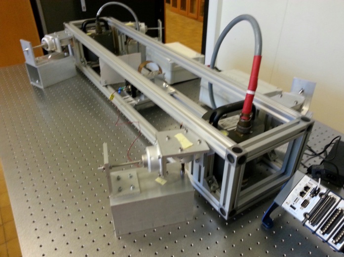
Fig 1. Picture of the active isolation system.
Control strategy
In order to decrease the cross coupling between the supports, a first concept has been studied, where each leg was constituted by an actuator in series with an inertial sensor. The idea was to use SISO decentralized controller in each leg, i.e. each actuator compensates the absolute displacement of the quadrupole, measured in the direction of the actuator with an inertial sensor mounted in series with the actuator. While very attractive to reduce the coupling between axes, it presents a couple of disadvantages: it is not straightforward to mount an inertial sensor in series with an actuator, the four vertical sensors are redundant, the configuration does not guarantees the stability of the controller, and it is difficult to develop small and precise inertial sensors. For these reasons, we have decided to use a high resolution inertial sensor [3] (NOSE in Fig. 3) only at low frequency for centralized inertial control and replace it at high frequency by local force feedback in each mount, as shown in Fig. 2, where i=1,..,8. The method has been published in [4].
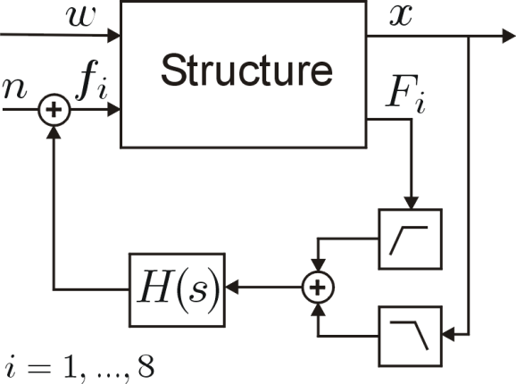
Fig 2. Closed loop bloc diagram. The strategy combines a centralized inertial control at low frequency, and decentralized force control loops in each active leg.
Each active mount is composed of a piezoelectric stack actuator Cedrat-Technologies APA100M, in series with a metallic suspension Paulstra 7002-JA to offer passive isolation at high frequency (Fig.3A). This configuration offers the interesting property to be completely compatible with the accelerator. Each actuator is divided in two parts: one is used as actuator, the other one is used a force sensor; both constitute a dual pair.
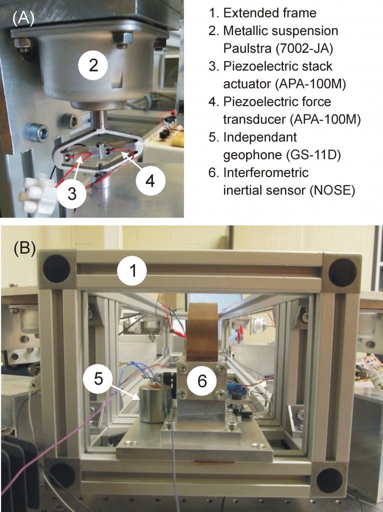
Fig 3. Picture of the experimental set-up. (A) One active leg, constituted of a dual pair of piezoelectric actuator/sensor, in series with a metallic suspension. (B) Picture of the interferometric inertial sensor (NOSE) used in the feedback loop, and of the witness geophone used to assess the closed loop performance.
The control strategy has been implemented in a Dspace DS1103 at 5kHz. At this stage, only the vertical direction has been tested. In order to remain above the noise floor of the witness geophone, random noise (n) is injected in the actuators, and the equipment motion is measured by a geophone (x). Figure 4 shows the transmissibility between n and x when the controller is turned off (Toff) and turned on (Ton). The feedback operation reduces the transmitted motion by three orders of magnitudes. The performance is limited by the geophone noise, but not by feedback stability issues.
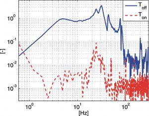
Fig 4. Vertical transmissibility between the noise (n) injected in the actuator and the structural vibrations measured by the witness geophone (x), integrated, and normalized, when the controller is turned off (Toff) and turned on (Ton).
Related references
[1] COLLETTE C., JANSSENS S. and TSHILUMBA D., Control strategies for the final focus of future linear particle collider, Nuclear instruments and methods in physics research section A , 2012, vol.684, 7-17. [PDF]
[2] COLLETTE C., FERNANDEZ-CARMONA P., JANSSENS S., ARTOOS K., GUINCHARD M., HAUVILLER C., Nano-Motion Control of Heavy Quadrupoles for Future Particle Colliders: An Experimental Validation, Nuclear instruments and methods in physics research section A, 2011, vol.643, 95-101. [PDF]
[3] COLLETTE C., NASSIF F., AMAR J., DEPOUHON C. and GORZA S.-P., Prototype of interferometric absolute motion sensor, Sensors and Actuators A: Physical, 2015, vol.224, 72-77. [PDF]
[4] COLLETTE C. and MATICHARD F., Sensor fusion methods for high performance active vibration isolation systems, Journal of sound and vibration, 2015, vol.342, 1-21. [PDF]