Active isolation of launcher’s vibration environment
Motivation
Sensitive payloads mounted on top of launchers are subjected to many sources of disturbances during the flight. The most severe dynamic loads arise from the ignition of the motors, gusts, the pressure fluctuations in the booster and from the separation of the boosters. In order to reduce the transmission of these dynamic forces, payloads can be mounted on passive isolators, which comprise passive elements to filter out high frequency loads, at the expense of harmful amplifications of the motion at low frequency due to suspension modes (where the payload bounce on the suspension stiffness). To some extent, the amplification can be by reduced increasing the damping with passive components. However, increasing the damping will in turn compromise the isolation, which is inherent to passive isolators. Several prototypes of active suspensions have been developed, including piezoelectric actuators or magneto-rheological fluids. However, so far, only passive isolators have been used in flight, because none of the active prototypes have been capable to fulfill the stringent requirements of space flight.
Concept of active isolator
The proposed concept of active isolator is composed of a compliant metallic structure, in which a sensor and a piezoelectric actuator is integrated [1]. An example of this configuration is shown in Fig. 1. As for flight-proven isolator, it consists of an elliptic metallic structure that plays the role of suspension. Additionally, a piezoelectric stack actuator has been placed inside the structure, along the horizontal axis of the ellipse. The stack is further divided in two parts, respectively used as actuator and as force sensor, and both constitute a perfectly collocated pair. In each mount, the actuator will be driven only by using the signal from the force sensor of the same mount. In the proposed configuration, it can also be noticed that the softening effect inherent to force control is limited by the metallic suspension, which will also continue to work as a passive isolator in case of failure of the piezoelectric stack. The advantages of this mount are:
- Modularity: The number and position of mounts will depend on the mass and inertia of the payload and the specific mechanical environment.
- The elliptical shape is working both as a suspension spring and as a mechanical amplifier for increasing the actuator range.
- Each unit is stand-alone (does not require any additional sensor).
- The control architecture use decentralized feedback loops in each active mount, which offers excellent stability margins.
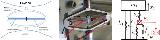
Fig 1. From left to right: Concept of active isolator; Picture of an APA 100M from Cedrat-Technologies used for the experiments (one piezoelectric stack is used as force sensor and the other one is used as actuator); Simplified model of a one d.o.f. payload mounted on such isolator.
Flexible payload mounted on three isolators
In the experimental setup used for the validation, the payload consists of two masses, connected through three flexible blades with a tunable length. The set-up is shown in Fig. 2, along with a simplified sketch showing only the vertical d.o.f. of the payload, mounted on one isolator.
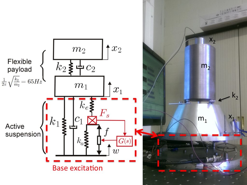
Fig 2. Right: Picture of the experimental set-up. It consists of a flexible payload mounted on a set of three isolators. Left: simplified sketch of the set-up, showing only the vertical direction.
The flexible resonance of the payload in the vertical direction has been tuned around 65 Hz. It corresponds to the resonance of m2 while m1 is blocked. The first six mode shapes and corresponding resonance frequencies are shown in Fig. 3. The set-up has been mounted on a passive optical table. A shaker has been mounted on the table top besides the set-up in order to excite it from the base as for the launcher.
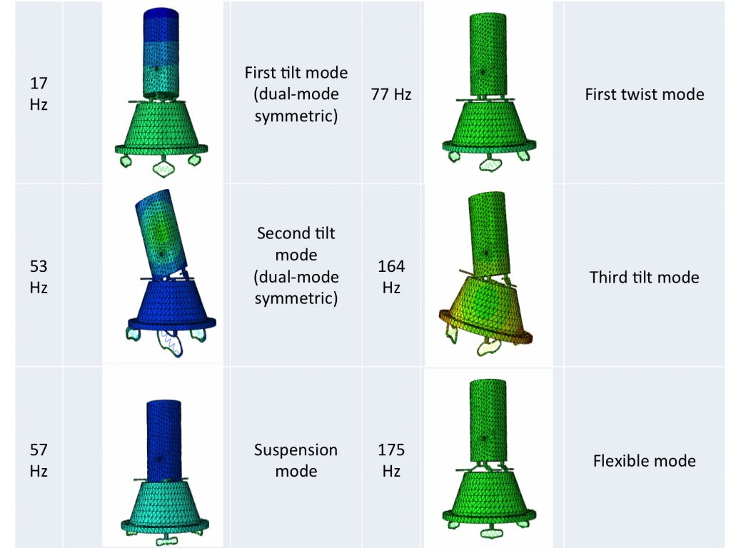
Fig 3. Mode shapes and corresponding resonance frequencies of the first 6 modes.
Two test campaigns have been conducted: one when the shaker excites the table in the vertical direction, and one when the shaker excites the table in the horizontal direction. For both campaigns, decentralized control loops have been used, as explained above. Typical experimental results are shown respectively in Fig. 4 for the vertical direction. Top left : Transfer function between the shaker noise and one force sensor ; Bottom left : integrated (downwards) RMS value of the force measured by one force sensor ; Top right : transmissibility between the table top w and m2 ; bottom right : Transmissibility between the table top w and m1. For both campaigns, one sees that both the suspension modes and the flexible modes of the payload can be critically damped. Furthermore, the fraction of the force transmitted to the payload that is measured by the force sensor is also significantly reduced by up to two orders of magnitudes around the resonances, and the RMS value is reduced by a factor 5.
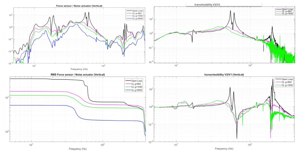
Fig 4. Vertical excitation. Top left: Transfer function between the shaker noise and one force sensor; Bottom left: integrated (downwards) RMS value of the force measured by one force sensor; Top right: transmissibility between the table top w and m2 ; bottom right : Transmissibility between the table top w and m1.
Related publications
[1] COLLETTE C., SOULEILLE A., LAMPERT T., RODRIGUES G. Active vibration isolation of sensitive payloads from launchers disturbances, ECSSMET conference, September 2016 (Toulouse, France).