Particle collider electromagnet stabilization and nano-positioning
Future linear particle collider
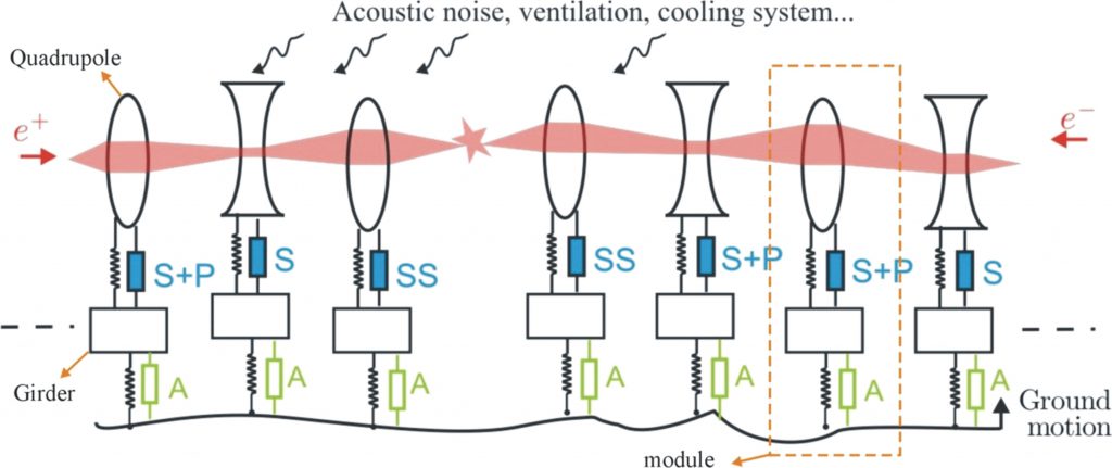
The Compact Linear Collider (CLIC) currently under study at CERN consists of a very large number (more than 20000) of identical sections (Fig. 1), the function of which is to accelerate and focus the beam of particles, towards the final section where the collision takes place.

Fig 1. Schematic view of the CLIC under study at CERN (due in 2023), consisting of more than 20000 modules.
In this future machine, electrons and positrons will be accelerated in two linear accelerators to collide at the interaction point with an energy of 0.5 to 3 TeV . To acquire such a high energy, the total length of the facility should to be up to 48 km. This linear accelerator will consist of a succession of accelerating structures and heavy electromagnets (quadrupoles). The former are used to accelerate the particles to increase their energy; the latter are used to maintain the beam inside the vacuum chamber (alternating gradient) and to reach the required luminosity at the collision point.
CLIC Stability requirements
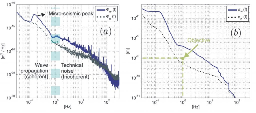
In a particle collider, any oscillation of one quadrupole deflects the beam, and reduces the luminosity. For CLIC, it has been estimated that the integrated Root Mean Square (RMS) of the vertical displacement, sx(f), must stay below 1 nm above 1 Hz to ensure sufficient performances. Similarly, it must stay below 5 nm in the lateral direction. This concerns about 2000 quadrupoles per beam line. Figure 2(a) shows the typical power spectral density in the LHC tunnel, Fw(f), and the power spectral density of the measurement noise, Fn(f). Figure 2(b) shows the corresponding integrated RMS curves. One sees on this figure that, in order to reach the objective of stability, one needs to design a support which reduces the ampltitude of the ground motion by roughly a factor four in the frequency range between 1 and 20 Hz. Below 1 Hz, the ground motion corresponds essentially to coherent (micro-seismic) waves propagating on the surface of the terrestrial crest; above 20 Hz, the ground motion does not provide any significant contribution to the integrated RMS at 1 Hz.

Fig 2. Typical power spectral density of the ground vibration in the LHC tunnel, and power spectral density of the measurement noise; (b) Integrated RMS vertical displacement of the ground in the LHC tunnel, integrated RMS of the sensor noise, and objective of the stabilisation.
Besides stability, the supports have also to fulfill these additional requirements:
- About 80 of these quadrupoles should have the capability to move by steps of some tens of nanometers every 20 ms, with a precision of +/ – 1nm, in the vertical and the lateral direction.
- The size of the tunnel is very restricted, and the space available for the mounts should not exceed a height of 15 cm.
- The direct environment of the future CLIC collider is subjected to radiations and stray magnetic fields. In order to ensure a full compatibility with this environment, this requirement excludes the use of electromagnetic equipment (electromagnetic actuators and sensors using coils likes commercial seismometers).
- The quadrupoles are pre-aligned by an alignment system that is located under the stabilization system. This pre-alignment is achieved with a micrometer precision. The stabilization system should be compatible with this alignment system, i.e. it should not alter the pre-alignment. This means that the stabilization system should be stiff, and that the displacements imposed by the alignment system should be precisely measured.
- In operating conditions, the quadrupoles are also subjected to several types of disturbances, commonly referred to as technical noise: acoustic noise, cooling system, ventilation. The supports should accordingly ensure a sufficient robustness to the external forces generated by these disturbances.
- The support should allow a temperature change of about 25 K during transients. Features should be implemented to protect the actuating system during transport and handling.
Experimental set-up
A priori, the first requirement of the list is conflicting with the stability. The positioning requires mounting the quadrupoles on strong actuators, to allow a fast motions at 50 Hz of the heavy mass, and also to ensure a sufficient robustness to technical noise. On the other hand, the stability suggests using a soft support, in order to benefit from the passive isolation at high frequency. In order to comply with all of these requirements using a unique support, an original concept, based on inclined active legs, has been introduced, and validated experimentally on a test bench, presented in the next section.
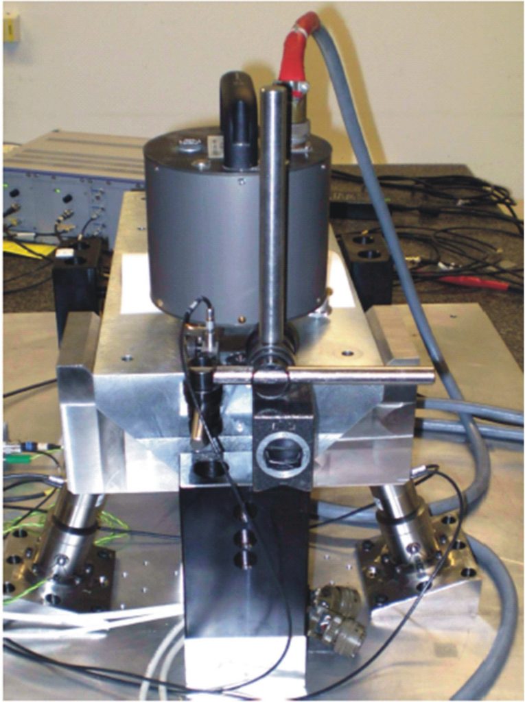
The test bench consists of a compact mass mounted on the two active legs (Fig.3). The legs are basically constituted of high voltage piezo-electric stack actuators, mounted with custom built flexible joints at both ends. One end is fixed on the mass, the other end is fixed on a straightened aluminium frame. The vibrations are measured with two seismometers, one on the plate and one on the mass. Both of them measure the velocity in the vertical direction and the horizontal direction (perpendicular to the main axis of the mass).

Fig. 3. (a) Model and (b) picture of the two d.o.f. test bench.
The test bench has been placed in a quiet tunnel at CERN (ISR-I8) where the amplitude of the ground motion is similar to the values measured in the LHC tunnel. Day and night variations allow to study the test bench with a background varying between 2 and 7 nm vertical integrated RMS at 1 Hz. The two following sections present respectively the stabilization and nano-positioning experimental performances of the test bench in this environment.
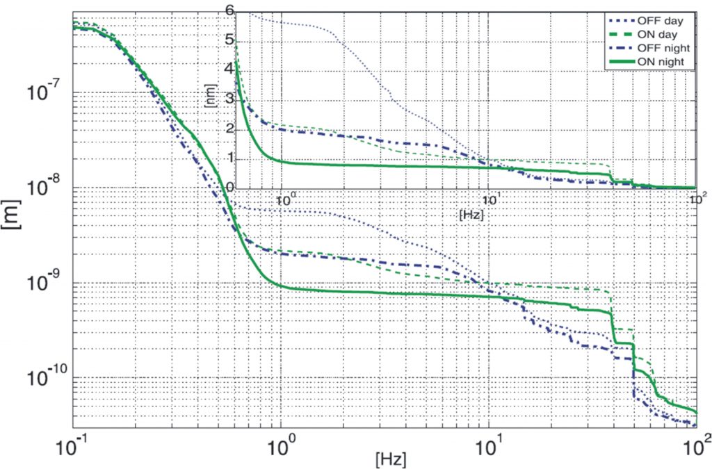
The control strategy adopted to stabilize the mass is based on the sky-hook spring method. It uses an additional oscillator, called inertial reference, to measure the absolute displacement of the mass and actively stiffen the system (Fig. 3(a)). It results in a reduction of the vibrations transmitted for frequencies below the resonance of the suspension. Compared with passive isolation, the main advantage of this strategy is to combine very low frequency isolation and good robustness to external disturbances. Figure 4 shows the corresponding integrated RMS vertical displacement of the top seismometer for two experiments, one performed during the day and one performed during the night. During the day, at 1 Hz, one sees that the feedback control has reduced sx(f) from 5.7 nm to 2.1 nm, i.e. a reduction by a factor 2.5. During the night, when the ground motion is even lower, sx(f) is reduced from 2 nm to 0.9 nm at 1 Hz, and 0.7 nm at 4 Hz.

Fig. 4. Comparison of integrated RMS of the mass displacement, when the controller is ON and OFF, during the day and during the night.
In order to test the nano-positioning capability of the test bench, two time histories have been used to command the two actuators. The corresponding displacement of the mass has been measured in the lateral and vertical direction by a capacitive gauge, and is shown in Fig. 5(a). Figure 5(b) shows the corresponding extensions of the legs after multiplication by the jacobian matrix J, linking the leg extensions to the reference frame (x,y). Figure 5(c) shows the resulting trajectory of the mass in the vertical plane, measured by a capacitive gauge.
More information about the project can be found on the CLIC nano stabilisation web page.

Fig. 5. Positioning experiment: (a) Time histories of the vertical (solid line) and lateral (dashed line) displacement of the mass measured by the capacitive gauge; (b) Extension of the legs after multiplication by J; (c) Resulting trajectory of the mass in the vertical plane.
Related publications
[1] FERNANDEZ-CARMONA P., ARTOOS K., COLLETTE C., ESPOSITO M., GUINCHARD M., JANSSENS S., KUZMIN A., and MORON BALLESTERA R., Study of the hybrid controller electronics for the nano-stabilization of mechanical vibrations of CLIC quadrupoles, Journal of Instrumentation, 2011, vol.6, C12023.
[2] COLLETTE C., FERNANDEZ-CARMONA P., JANSSENS S., ARTOOS K., GUINCHARD M., HAUVILLER C., Nano-Motion Control of Heavy Quadrupoles for Future Particle Colliders: An Experimental Validation, Nuclear instruments and methods in physics research section A, 2011, vol.643, 95-101. [PDF]
[3] ARTOOS K., COLLETTE C., FERNANDEZ-CARMONA P., GUINCHARD M., HAUVILLER C., JANSSENS S., KUZMIN A., SLAATHAUG A., Study of the electronics architecture for the mechanical stabilisation of the quadrupoles of the CLIC linear accelerator, Journal of Instrumentation, 2010, vol.5, C11014.
[4] COLLETTE C., ARTOOS K., GUINCHARD M. and HAUVILLER C., Seismic response of linear accelerators, Physical reviews special topics: accelerators and beams, 2010, vol.13, 072801. [PDF]
[5] COLLETTE C., ARTOOS K., KUZMIN A., SYLTE M., GUINCHARD M. and HAUVILLER C., Active quadrupole stabilization for future linear particle colliders, Nuclear instruments and methods in physics research section A, 2010, vol.621 (1-3), 71-78. [PDF]


